Direct Connect
Direct Connect


Document

- Documentation
 Direct ConnectBest PracticesCloud data interconnectionInterconnecting cloud data across CENs via Direct Connect Gateway with custom ASN
 Copy page
 Download PDF
Cloud data interconnection
Interconnecting cloud data across CENs via Direct Connect Gateway with custom ASN
Copy pageDownload PDFInterconnecting cloud data across CENs via Direct Connect Gateway with custom ASN
This section describes how to enable data interchange between multiple Virtual Private Clouds (VPCs) via Direct Connect (DC) and Cloud Enterprise Network (CEN).
tip
This scenario applies when multiple VPCs in the same region cannot interconnect directly through CENs.
Scenarios
An enterprise has activated multiple cloud services in China (Beijing), deployed in VPC-01 and VPC-02 respectively. The business switches in the on-premises data center support interconnection. The enterprise expects VPC-01 (CIDR block: 10.122.100.0/24) to communicate through the DC with VPC-02 (CIDR block: 100.122.200.0/24). We recommend using multiple CENs and DC Gateways with custom Autonomous System Number (ASN) to interconnect cloud and on-premises services, enabling data intercommunication by on-premises switches. The overall network design is shown in the diagram below:
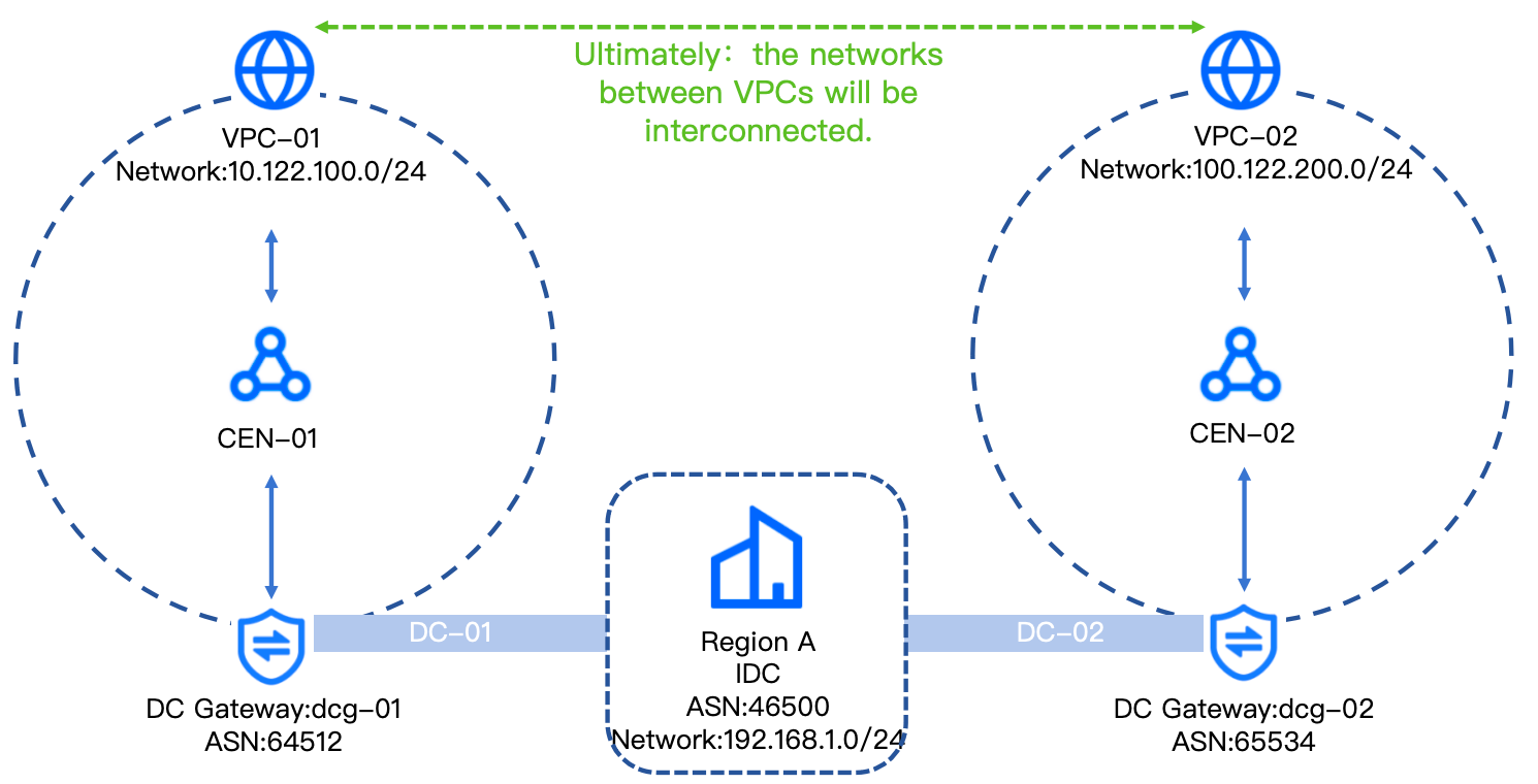
Network planning
DC interconnection | DC-01 (VIF-01) | DC-02 (VIF-02) |
Cloud gateway peer IP | 10.122.100.1/24 | 100.122.200.3/24 |
Your gateway IP | 10.122.100.2/24 | 100.122.200.4/24 |
VLAN ID | 10 | 20 |
tip
- Both custom ASNs for DC Gateways must be different and neither can be 137718.
- If the DC is connected to different switches, ensure network connectivity between the two switches.
Prerequisites
- You have created VPCs (VPC-01 and VPC-02) and their subnets. For specific procedure, see Creating a VPC.
- You have planned CIDR blocks to avoid conflicts between VPC-01 and VPC-02. For more about network planning, see Network planning and design.
Procedure
Step 1: Create a DC Connection
Implement two DC Connections. For details, see Creating a Direct Connect Connection. The DC Connections in this example are as follows:
- Between the data center and VPC-01: DAS235_port01_conn in China (Beijing);
- Between the data center and VPC-02: DAS681_port01_conn in China (Beijing).
Step 2: Create a DC Gateway
- Log in to the Direct Connect Gateway console.
- In the top menu bar, select the region: China (Beijing).
- Click Create DC Gateway.
- Configure the DC Gateway (dcg-01) based on the table below.
- ParameterDescriptionSample valueRegionsThe region where the DC Gateway is deployed. It must match the region of the DC Connection.China (Beijing)NameSet a name for the DC Gateway.dcg-01ASNSet an ASN for the DC Gateway.64512IPv6Enable IPv6 as needed.DisableProjectSelect the project to which the new DC Gateway belongs.Project-testAgreementFollow the console guidance to review and accept Legal.Check
- After confirming all parameters are correct, click Buy now to complete the action.
- Click Go to console to return to the Direct Connect Gateway console. You can view the new DC Gateway (dcg-01) in the DC Gateway list.
- Repeat steps 1 to 6 to create another DC Gateway (dcg-02), with configurations listed in the table below.
- ParameterDescriptionSample valueRegionsThe region where the DC Gateway is deployed.China (Beijing)NameSet a name for the DC Gateway.dcg-02ASNSet an ASN for the DC Gateway.65534IPv6Enable IPv6 as needed.DisableProjectSelect the project to which the new DC Gateway belongs.Project-testAgreementFollow the console guidance to review and accept Legal.Check
Step 3: Create a Virtual Interface
- Log in to the DC Virtual Interface console.
- Click Create DC Virtual Interface.
- See the table below to configure the Virtual Interface of the DC Connection: DAS235_port01_conn (DC-01).
-
- Click Create to complete the action.
- Repeat steps 1 to 4 to create a Virtual Interface for another DC Connection: DAS681_port01_conn (DC-02), with configurations listed in the table below.
-
Step 4: Create a CEN and load the network instance
- Log in to the CEN console.
- Click Create CEN.
- Configure the CEN Instance based on the table below and load the VPC instance: VPC-01.
- ParameterValueBasic informationNameCEN-01Network InstancesAttaching a network instanceEnableRegionsChina (Beijing)Instance typeVirtual Private Cloud (VPC)Network InstancesProject-test|VPC-01More informationProjectProject-test
- Click Create to complete the action.
- In the list of CEN instances, click the target instance's name: CEN-01.
- In the Network Instances tab, click Attach Network Instance.
- The Attach Network Instance window pops up. Configure the information of the DC Gateway instance to be loaded, and then click Attach to complete the action.
- ParameterValueAccountMy accountRegionsChina (Beijing)Instance typeDirect Connect GatewayNetwork Instancesdcg-01
- Repeat steps 1 to 7 to create another CEN (CEN-02) and load VPC-02, with configurations listed in the table below.
- ParameterValueBasic informationNameCEN-02Network InstancesAttaching a network instanceOnRegionsChina (Beijing)Instance typeVirtual Private Cloud (VPC)Network InstancesProject-test|VPC-02More informationProjectProject-test
- Repeat steps 5 to 7 to load the DC Gateway (dcg-02) into CEN-02, with configurations listed in the table below.
- ParameterValueAccountMy accountRegionsChina (Beijing)Instance typeDirect Connect GatewayNetwork Instancesdcg-02
Step 5: Add a security group rule to a VPC
Allow the IPs of the on-premises data center and peer VPCs in the security groups of both VPC-01 and VPC-02.
- Log in to the Virtual Private Cloud console.
- In the top menu bar, select the region: China (Beijing).
- In the VPC list, search for the target VPC: VPC-01.
- Click VPC-01 to enter its details page, then click Security Group.
- In the security group list, click Edit rule in the Actions column of the target security group.
- On the Access rules tab, select Inbound rules, and click Add rule.
- Add two inbound rules based on the image below, allowing CIDR blocks of the data center (192.168.1.0/24) and VPC-02 (100.122.200.0/24) to access VPC-01.
- Repeat steps 1 to 6, add two inbound rules in VPC-02’s security group, allowing CIDR blocks of the data center (192.168.1.0/24) and VPC-01 (10.122.100.0/24) to access VPC-02.
Step 6: Configure on-premises routing
Configure routing and BFD on the on-premises data center. Using the example of connecting two DC Connections to two switches (assumed Switch 1 and Switch 2) on the data center, this demonstrates how to configure BGP route and BFD separately on both switches.
Reference commands
Configuration on Switch 1 of the data center:
bgp 46500 //46500 is the BGP neighbor ASN on the local IDC side.
peer 10.122.100.1 as-number 64512 //10.122.100.1 is the local (cloud gateway) peer IP address of DC-01; 64512 is the ASN of dcg-01.
peer 10.122.100.1 password simple 123456**** //BGP key.
peer 10.122.100.1 bfd
network 192.168.1.0 255.255.255.0 // Private CIDR block and subnet mask of the IDC.
interface HGE1/1/1 // DC interface
bfd detect multiplier 3 // BFD detection time multiplier.
bfd min-transmit-interval 1000 //The minimum interval for sending single-hop BFD control packets.
bfd min-receive-interval 1000 // The minimum interval for receiving single-hop BFD control packets.
Configuration on Switch 2 of the data center:
bgp 46500 //46500 is the BGP neighbor ASN on the local IDC side.
peer 100.122.200.3 as-number 65534 //100.122.200.3 is the local (cloud gateway) peer IP address of DC-02. 65534 is the ASN of dcg-02.
peer 100.122.200.3 password simple 123456**** //BGP key.
peer 100.122.200.3 bfd
network 192.168.1.0 255.255.255.0 //Private CIDR block and mask of on-premises IDC-01.
interface HGE1/1/1 // DC interface.
bfd detect-multiplier 3 // BFD detect multiplier.
bfd min-transmit-interval 1000 //Minimum interval for sending single-hop BFD control packets.
bfd min-receive-interval 1000 //Minimum interval for receiving single-hop BFD control packets.
Step 7: Test connectivity
Log in to any Elastic Compute Service (ECS) instance under VPC-01 in China (Beijing). Ping the IP address (within the interconnected CIDR block) of an ECS instance in VPC-02. A successful ping response confirms network connectivity between VPC-01 and VPC-02.
Last updated: 2026.08.24 11:30:50
All rights reserved © Beijing Volcano Engine Technology Co., Ltd2024
