Transit Router
Transit Router


Document

- Documentation
 Transit RouterBest PracticesImplementing interconnectivity between independent VPCs and a data center (same account, cross-region)
 Copy page
 Download PDF
Best Practices
Implementing interconnectivity between independent VPCs and a data center (same account, cross-region)
Copy pageDownload PDFImplementing interconnectivity between independent VPCs and a data center (same account, cross-region)
This topic describes how to configure Transit Router (TR) for cross-region connectivity under the same account, allowing different Virtual Private Clouds (VPCs) to access the same on-premises data center while remaining isolated from each other.
Scenarios
By integrating with VPN Connect or Direct Connect (DC) services, the TR flexibly enables interconnectivity and isolation between separate VPCs and an on-premises data center.
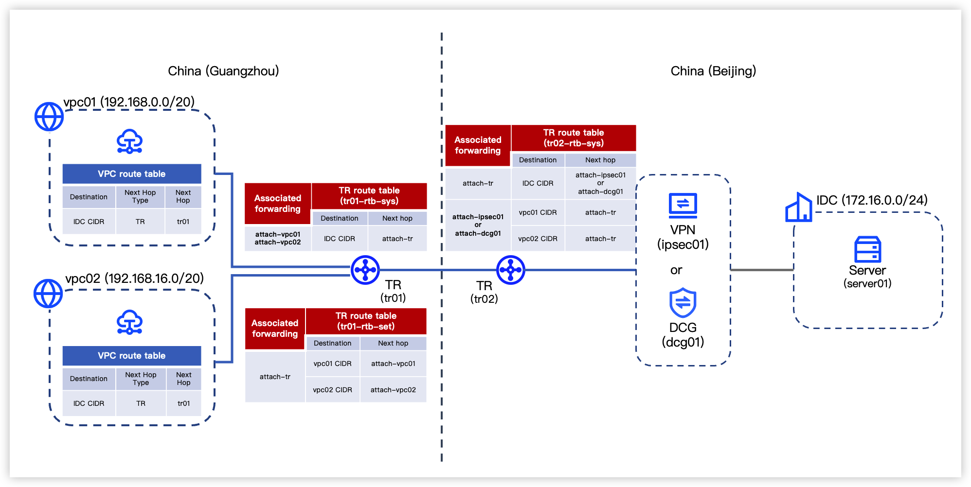
In the diagram below, all cloud resources such as VPCs and TRs belong to the same account. Two VPCs in China (Guangzhou) can access the data center in China (Beijing) via TR, while the two VPCs cannot access each other.

Data planning
Before configuration, plan the CIDR blocks, routes, and other data parameters for each network resource in the diagram as shown below.
tip
Routes in the VPC route tables illustrated below can be manually configured or automatically synchronized. This example uses auto publishing.
- Virtual Private Cloud
-
- VPN Connect
-
- Direct Connect
-
- Transit Router
- The route planning is illustrated above. For details, see TR Route configuration planning.
- On-premises data center
- RegionSubnetECS namePrivate IP addressPublic IP addressChina (Beijing)172.16.0.0/24server01172.16.0.1012.XX.XX.10
Prerequisites
- You have created necessary VPCs and their subnets. For procedure, see Creating a VPC.
- You have created Elastic Compute Service (ECS) instances in all VPCs. For procedure, see Purchasing an ECS instance.
- You have completed the following configuration based on the service type connecting to the on-premises data center. For parameters, see Data planning.
- VPN: See Creating a Customer Gateway and create a customer gateway (named cgw01) required for this scenario.
tip
The IPsec-VPN connection in this example uses dynamic routing, ensuring that your customer gateway supports BGP and that valid ASNs have been configured for associated resources and the customer gateway.
- DC: Follow the first three steps in Configuring a DC Connection to create a DC Connection, DC Gateway, and DC Virtual Interface. Then complete private route configuration in the on-premises data center by seeing Configuring on-premises routing.
- You have obtained the IP address of the server in the data center and ensured the server is properly operational.
Configuration procedure
tip
This example only covers required parameters. Leave other parameters at their default values.
Step 1: Configure a TR instance in China (Guangzhou)
In this step, you need to create one TR instance, one custom route table and two network instance attachments for the TR. For procedure, see Configure a TR instance in China (Guangzhou).
- Create a TR instance.
- Create a TR instance (named tr01) in China (Guangzhou) to host the TR service.
tip
- In this example, assign 64512 to tr01 as its ASN.
- When you create a TR instance, the system automatically creates a system route table for it to forward access traffic from vpc01 and vpc02 in the same region. The following uses tr01's system route table (named tr01-rtb-sys) as an example.
- Create a TR custom route table.
- Create a custom route table (named tr01-rtb-set) for tr01 to forward access traffic from the inter-region attachment.
- Create a network instance attachment and configure routing
- Create two network instance attachments for tr01 (named attach-vpc01 and attach-vpc02) to connect with respective VPC instances (vpc01 and vpc02) in the same region.
- View TR and VPC routes
- tr01-rtb-sys contains no entries, while the routes in tr01-rtb-set are listed below.
-
- Since the routes in tr01-rtb-sys are automatically published to the vpc01 and vpc02 route tables, the routes in those tables remain unchanged.
Step 2: Configure a TR instance in China (Beijing)
- Create a TR instance.
- Create a TR instance (named tr02) in China (Beijing). For procedure, see Creating a Transit Router instance.
tip
- In this example, assign 64513 to tr02 as its ASN.
- When you create a TR instance, the system automatically creates a system route table for it. The following uses tr02's system route table (named tr02-rtb-sys) as an example.
- Create a network instance attachment.
- Create the appropriate network instance attachment based on the resource type connecting to the on-premises data center. For procedure, see Creating a VPN attachment or Creating a DC Gateway attachment.
-
- Basic configuration
-
- Route configuration
-
tipAfter the VPN attachment is created, complete the VPN configuration on the server in the on-premises data center, ensuring it is consistent with the IPsec-VPN connection settings. For parameters, see Data planning.Configure the basic information, network instance, and routing information for the network instance attachment based on the table below.
- View tr02-rtb-sys, confirming that the route table has learned routes pointing to the data center from the DC or VPN.
- When connecting to the data center via DC, tr02-rtb-sys should have learned the routes listed in the table below.
-
- When connecting to the data center via VPN, tr02-rtb-sys should have learned the routes listed in the table below.
-
-
Step 3: Configure inter-region bandwidth
- Create a bandwidth package.
- Create a bandwidth package (named trbp01) to provide bandwidth resources for the inter-region attachment. For procedure, see Creating a TR bandwidth package.
- Create an inter-region attachment.
- Create an inter-region attachment to link the TR instance in China (Guangzhou) and the TR instance in China (Beijing). For procedure, see Creating an inter-region attachment.
- This example uses the TR instance in China (Guangzhou), tr01, as Local TR to create an inter-region attachment. Specific parameters are shown in the table below.
- ParameterDescriptionExampleNameType the name for the inter-region attachment.attach-trBandwidth packageAdd to the created bandwidth package (trbp01) and allocate bandwidth.Checked, trbp01, 2 MbpsLocal associated route tableEnable associated forwarding to allow the local TR instance (tr01) to forward access traffic from inter-region attachment according to tr01-rtb-set.Enabled, tr01-rtb-setRemote TR association forwardingEnable associated forwarding to allow the peer TR instance (tr02) to forward access traffic from the inter-region attachment according to tr02-rtb-sys.Enabled, tr02-rtb-sysLocal TR route learningEnable route learning to allow tr01-rtb-sys to automatically learn routes from the peer TR route table (tr02-rtb-sys) associated with forwarding.Enabled, tr01-rtb-sysRemote TR route learningEnable route learning to allow the specified TR route table (tr02-rtb-sys) to automatically learn routes from the local TR route table (tr01-rtb-set) associated with forwarding.Enabled, tr02-rtb-sys
- View TR and VPC routes
- The routes in the TR route table (tr01-rtb-set) remain unchanged.
- The routes in TR route tables (tr01-rtb-sys and tr02-rtb-sys) vary depending on the type of network resources connected to the data center.
- When connecting to the data center via DC, tr02-rtb-sys should have learned the routes listed in the table below.
-
- When connecting to the data center via VPN, tr02-rtb-sys should have learned the routes listed in the table below.
-
- The system route tables of vpc01 and vpc02 have learned the routes to the data center's CIDR block from the TR, as shown in the table below.
-
Result validation
- Log in to the ECS instance in vpc01. For procedure, see Logging on to a Linux instance or Logging on to a Windows instance.
- Execute the ping command to connect to respective servers in vpc02 and the on-premises data center. Verify that vpc01 communicates with the data center but not with vpc02.
- Similarly, log in to the ECS instance in vpc02 and verify connectivity between vpc02 and the server in the data center.
Last updated: 2026.09.01 11:37:15
All rights reserved © Beijing Volcano Engine Technology Co., Ltd2024
