Transit Router
Transit Router


Document

- Documentation
 Transit RouterBest PracticesOptimizing paths for different subnets within a VPC to reach an on-premises data center via Direct Connects
 Copy page
 Download PDF
Best Practices
Optimizing paths for different subnets within a VPC to reach an on-premises data center via Direct Connects
Copy pageDownload PDFOptimizing paths for different subnets within a VPC to reach an on-premises data center via Direct Connects
This topic describes how to enable different subnets within a Virtual Private Cloud (VPC) to access an on-premises data center through different Direct Connect (DC) links.
Scenarios
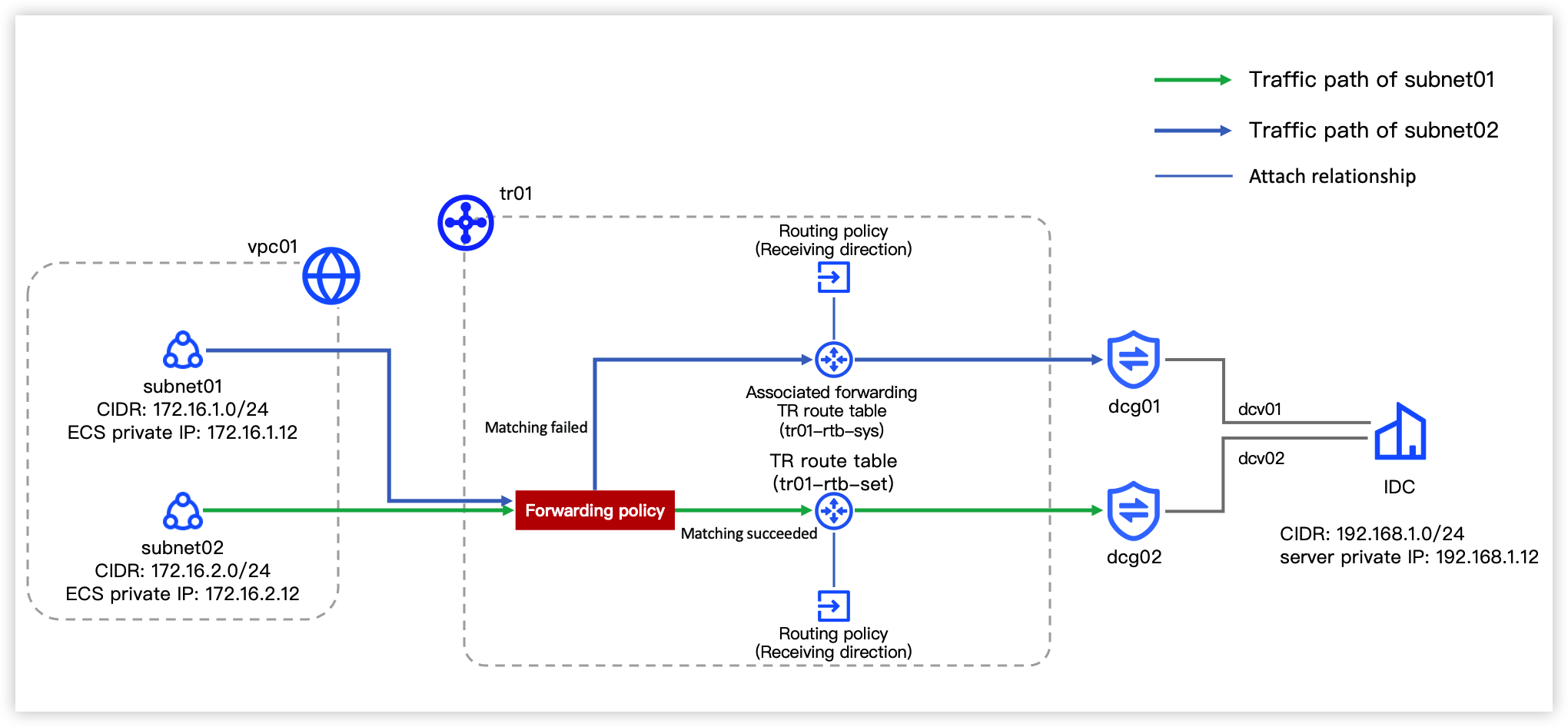
Transit Router (TR) offers rich routing capabilities. By configuring forwarding and route policies, traffic from different subnets within the same VPC can use separate links to access the on-premises data center, enabling active-standby failover configuration for DC links.
As shown in the networking scenario below, the subnet (subnet01) accesses the data center with dcv01 as the primary link and dcv02 as the secondary, while subnet02 accesses the data center with dcv02 as the primary and dcv01 as the secondary.
Prerequisites
You have properly connected the VPC and two DC Gateways to the TR instance and achieved interconnection between the VPC and the on-premises data center.
tip
The system route table of the TR instance is named tr01-rtb-sys and used as an example.
Data planning
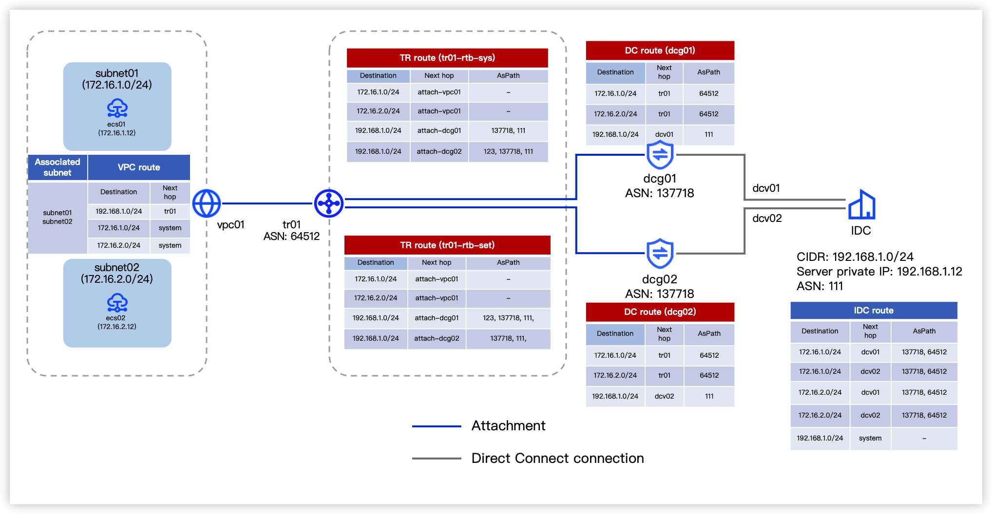
Before configuration, plan the CIDR blocks, routes, and other data parameters for each network resource in the diagram as shown below.
Configuration procedures
Step 1: Create a TR route table and configure routing
- Follow the procedure in Creating a route table to create a TR route table (named tr01-rtb-set).
- Follow the procedure in Create a route learning rule to configure routes for tr01-rtb-set. Select the attachment types as the VPC (vpc01), DC Gateways (dcg01 and dcg02), and the TR instance in sequence.
Step 2: Configure route policy
- Follow the procedure in Creating a route policy to create two inbound route policies. The specific policy entries are shown in the table below.
- Route policy 1
-
- Route policy 2
-
- Associate the two route policies from the previous step to the respective TR route tables (tr01-rtb-sys and tr01-rtb-set) following the instructions in Associate a route policy to TR route table.
- Select the Route entry tab. Review that all routes with the next hop as the DC Gateway have routing property added, and the status of entries with longer AsPath becomes Not effective. The details are shown in the diagram below (using tr01-rtb-sys as an example).
Step 3: Configure forwarding policy
- Follow the procedure in Creating a forwarding policy to create one forwarding policy for the TR instance. The specific policy entries are shown in the table below.
-
- Follow the procedure in Configuring forwarding policy for an attachment to apply the forwarding policy from Step 1 to the VPC attachment. This enables the traffic from the subnet (subnet02) to be forwarded based on the TR route table (tr01-rtb-set).
Result validation
- Log in to Elastic Compute Service (ECS) instances in respective subnets (subnet01 and subnet02). For procedure, see Logging on to a Linux instance or Logging on to a Windows instance.
- Execute the following commands on both ECS instances to consecutively send data to the on-premises data center.
- The instance in subnet01
- Linux: ping -s 5000 -c 10000 192.168.1.12
- Windows: ping -l 5000 192.168.1.12 -t
- The instance in subnet02
- Linux: ping -s 10000 -c 10000 192.168.1.12
- Windows: ping -l 10000 192.168.1.12 -t
- Observe the monitoring metric "Attachment inbound bandwidth" of the attachment.
- Based on the commands set in step 2, the "Attachment inbound bandwidth" for attachments (attach-dcg01 and attach-dcg02) is approximately in a 1:2 ratio. This indicates that access traffic from subnet01 is forwarded via TR to dcg01 to access the on-premises data center, while traffic from subnet02 is forwarded via TR to dcg02 to access the data center.
Last updated: 2026.09.01 11:37:15
All rights reserved © Beijing Volcano Engine Technology Co., Ltd2024
