Transit Router
Transit Router


Document

- Documentation
 Transit RouterBest PracticesImplementing interconnectivity and isolation between specified VPCs
 Copy page
 Download PDF
Best Practices
Implementing interconnectivity and isolation between specified VPCs
Copy pageDownload PDFImplementing interconnectivity and isolation between specified VPCs
This topic describes how to configure the Transit Router (TR) to meet the networking requirements for interconnectivity and isolation between multiple Virtual Private Clouds (VPCs).
Scenarios
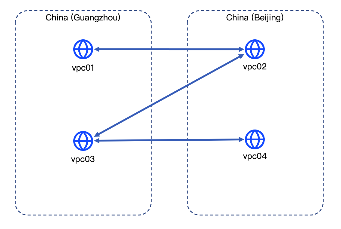
TR flexibly enables interconnectivity and isolation between multiple VPCs, whether they are in the same region or across different regions. You can implement network isolation by configuring route policies or using multiple TR route tables. This example uses a cross-region scenario to demonstrate how to use the TR to achieve interconnectivity shown in the diagram below.
tip
To achieve interconnectivity and isolation between multiple VPCs in the same region, first complete TR route planning by seeing Route planning, and then follow the configuration procedure described in Implementing private interconnectivity and isolation between different VPCs (same account, same region).
Prerequisites
- You have created necessary VPCs and their subnets. For procedure, see Creating a VPC.
- You have created Elastic Compute Service (ECS) instances in all VPCs. For procedure, see Purchasing an ECS instance.
Data planning
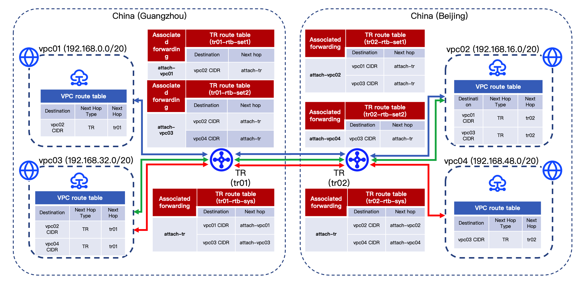
Before configuration, plan the data parameters for VPCs and TRs in the diagram, as shown below.
- VPC
-
- Transit Router
- The route planning is illustrated above. For details, see TR Route configuration planning.
Configuration procedures
tip
This example only covers required parameters. Leave other parameters at their default values.
Step 1: Configure a TR instance in China (Guangzhou)
- Create a TR instance.
- Create a TR instance (named tr01) in China (Guangzhou). For procedure, see Creating a Transit Router instance.
tip
When you create a TR instance, the system automatically creates a system route table for it to forward traffic from the inter-region attachment. The following uses tr01's system route table (named tr01-rtb-sys) as an example.
- Create a TR custom route table.
- Create two custom route tables for tr01 (tr01-rtb-set1 and tr01-rtb-set2) to forward traffic from respective attachments (attach-vpc01 and attach-vpc03). For procedure, see Creating a route table.
- Create a VPC attachment.
- Create two attachments for tr01 to connect vpc01 and vpc03 separately. For procedure, see Creating a VPC attachment.
- Basic configuration
-
- Route configuration
-
- View TR and VPC routes
- The custom route tables (tr01-rtb-set1 and tr01-rtb-set2) contain no entries, while the routes in tr01-rtb-sys are listed below.
-
- In this example, since the vpc01 route table learns routes from the tr01-rtb-set1, and the vpc03 route table learns from tr01-rtb-set2, routes in the vpc01 and vpc03 route tables are unchanged.
Step 2: Configure a TR instance in China (Beijing)
- Create a TR instance.
- Create a TR instance (named tr02) in China (Beijing). For procedure, see Creating a Transit Router instance.
tip
After the TR instance is created, the system automatically creates a system route table (to forward traffic from attach-Inter-region). Record the name of this system route table (tr02-rtb-sys). The following uses tr02-rtb-sys as an example.
- Create a TR custom route table.
- Create two custom route tables for tr02 (tr02-rtb-set1 and tr02-rtb-set2) to forward traffic from respective attachments (attach-vpc02 and attach-vpc04). For procedure, see Creating a route table.
- Create a network instance attachment.
- Create two attachments for tr02 to connect vpc02 and vpc04 separately. For procedure, see Creating a VPC attachment.
- Basic configuration
-
- Route configuration
-
- View TR and VPC routes
- The custom route tables (tr02-rtb-set1 and tr02-rtb-set2) contain no entries, while the routes in tr02-rtb-sys are listed below.
-
- In this example, since the vpc02 route table learns routes from the tr02-rtb-set1, and the vpc04 route table learns from tr02-rtb-set2, entries in the vpc02 and vpc04 route tables are unchanged.
Step 3: Configure inter-region bandwidth
- Create a bandwidth package.
- Create a bandwidth package (named trbp01) to provide bandwidth resources for the inter-region attachment. For procedure, see Creating a TR bandwidth package.
- Create an inter-region attachment.
- Create an inter-region attachment to link the TR instance in China (Guangzhou) and the TR instance in China (Beijing). For procedure, see Creating an inter-region attachment.
- This example uses the TR instance in China (Guangzhou), tr01, as Local TR to create an inter-region attachment. Specific parameters are shown in the table below.
- ParameterDescriptionExampleNameType the name for the inter-region attachment.attach-Inter-regionBandwidth packageAdd to the created bandwidth package (trbp01) and allocate bandwidth.Checked, trbp01, 2 MbpsLocal associated route tableEnable association forwarding, and specify that the local TR instance (tr01) uses tr01-rtb-sys to forward traffic from the inter-region attachment.Enabled, tr01-rtb-sysRemote TR association forwardingEnable association forwarding, and specify the peer TR instance (tr02) uses tr02-rtb-sys to forward traffic from the inter-region attachment.Enabled, tr02-rtb-sysLocal TR route learningEnable route learning to allow the specified TR route table to automatically learn routes from the peer TR route table (tr02-rtb-sys) associated with forwarding.tr01-rtb-set2Remote TR route learningEnable route learning to allow the specified TR route table to automatically learn routes from the local TR route table (tr01-rtb-sys) associated with forwarding.tr02-rtb-set1
- Configure a TR route pointing to the inter-region attachment.
- Add the static route pointing to the inter-region attachment to respective custom route tables (tr01-rtb-set1 and tr02-rtb-set2). Specific routes are listed in the table below. For procedure, see Create a static route.
- Route table (tr01-rtb-set1)
-
- Route table (tr02-rtb-set2)
-
- View TR and VPC routes
- The routes in tr01-rtb-set1 and tr01-rtb-set2 are listed in the following table.
-
- The routes in tr02-rtb-set1 and tr02-rtb-set2 are listed in the following table.
-
- In this example, the VPC route tables learn routes from respective tr route tables: vpc01 from tr01-rtb-set1, vpc03 from tr01-rtb-set2, vpc02 from tr02-rtb-set1, and vpc04 from tr02-rtb-set2. The routes in each VPC route table are listed in the following table.
-
Step 4: Configure a VPC custom route (optional)
warning
- In this example, this step is not required since Auto Publish Route is enabled when creating the attachment in Step 1 and Step 2.
- If you do not enable Auto Publish Route at creation, follow the steps below to configure a custom route for respective VPCs.
- Click the instance name in the Name/ID column.
- In the Associated resources section, click the digit to the right of VPC resource > Route Table.
- Click the target route table name.
- In the section below Basic information, select the Route Entry > Custom route tab.
- Click Add route, and configure the route based on the table below.
- Route configuration for vpc01
- No.Destination CIDRNext Hop typeNext Hop1192.168.16.0/20TRtr01
- Route configuration for vpc02
- No.Destination CIDRNext Hop typeNext Hop1192.168.0.0/20TRtr022192.168.32.0/20TRtr02
- Route configuration for vpc03
- No.Destination CIDRNext Hop typeNext Hop1192.168.16.0/20TRtr012192.168.48.0/20TRtr01
- Route configuration for vpc04
- No.Destination CIDRNext Hop typeNext Hop1192.168.32.0/20TRtr02
- Click Create to complete configuration.
- Review the custom routes in each VPC route table as shown in the table below.
-
Result validation
- Log in to the ECS instance in vpc01. For procedure, see Logging on to a Linux instance or Logging on to a Windows instance.
- Execute the ping command to connect to respective servers in vpc02, vpc03 and vpc04, verifying that vpc01 communicates with vpc02, but not with vpc03 or vpc04.
- Similarly, log in to respective ECS instances in vpc02, vpc03 and vpc04, and execute the ping command to connect other ECS instances, verifying interconnectivity and isolation between VPCs.
- vpc02 communicates with vpc01 and vpc03, but not with vpc04.
- vpc03 communicates with vpc02 and vpc04, but not with vpc01.
- vpc04 communicates with vpc03, but not with vpc01 or vpc02.
Last updated: 2026.09.01 11:37:15
All rights reserved © Beijing Volcano Engine Technology Co., Ltd2024
