You need to enable JavaScript to run this app.
Transit Router

Transit Router

Copy page
Download PDF
Best Practices
Implementing interconnectivity between independent VPCs and a data center (cross-account, same region)
Copy page
Download PDF
Implementing interconnectivity between independent VPCs and a data center (cross-account, same region)
This topic describes how to configure Transit Router (TR) for cross-account connectivity in the same region, allowing different Virtual Private Clouds (VPCs) to access the same on-premises data center while remaining isolated from each other.​
Scenarios​
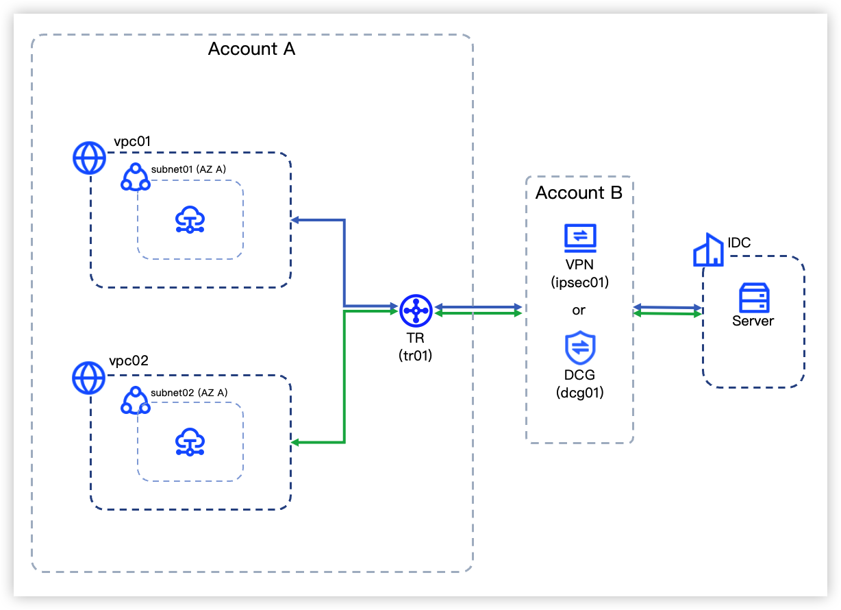
A company has deployed two VPCs in Region A. Both VPCs need to share the VPN Connect or Direct Connect (DC) resources owned by another account to access an on-premises data center. The two VPCs themselves must remain isolated from each other. This scenario can be implemented using TR, as illustrated in the following diagram.​
​​​
Data planning​
  • Select a region that is closest to the geographical location of the data center for VPN or DC. This example selects China (Beijing).​
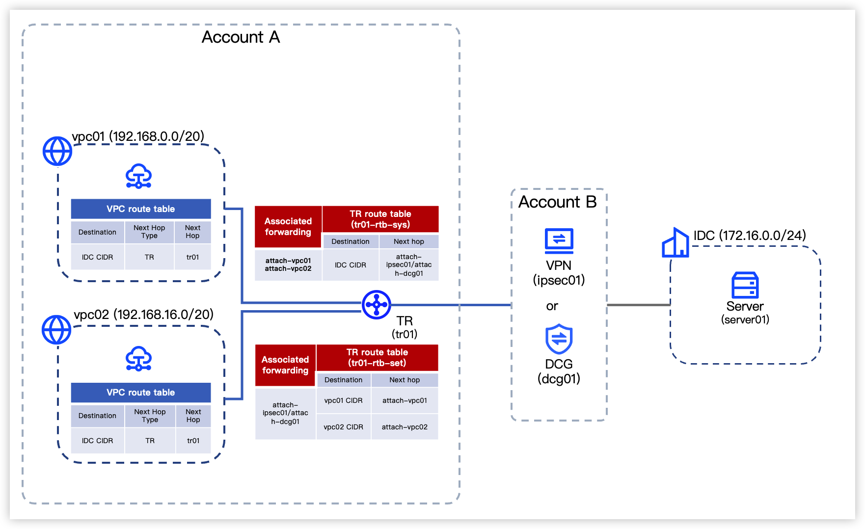
  • Before configuration, plan the CIDR blocks, routes, and other parameters for the network resources shown in the topology diagram.​
tip​
Routes in the VPC route tables illustrated below can be manually configured or automatically synchronized. This example uses auto publishing.​
​
​​​
  • Virtual Private Cloud​
  • ​
    Region​
    Account​
    Resource type​
    VPC CIDR block​
    CIDR block​
    Subnet information​
    China (Beijing)​
    Account A​
    VPC​
    vpc01​
    192.168.0.0/20​
    --​
    ​
    ​
    ​
    vpc02​
    192.168.16.0/20​
    --​
    ​
    ​
    Subnet​
    subnet01​
    192.168.0.0/24​
    • Affiliated availability zone: Availability Zone A​
    • ECS private IP: 192.168.0.10​
    ​
    ​
    ​
    subnet02​
    192.168.16.0/24​
    • Availability zone: Availability Zone A​
    • ECS private IP: 192.168.16.10​
    ​
  • VPN Connect​
  • ​
    Region​
    Account​
    Resource type​
    Resource name​
    IP address/CIDR block​
    Routing information​
    China (Beijing)​
    Account B​
    IPsec-VPN connection​
    ipsec01​
    • Tunnel CIDR block: 169.254.1.0/30​
    • Local Tunnel IP: 169.254.1.1​
    • Peer Tunnel IP: 169.254.1.2​
    • Pre-shared key: test@123​
    --​
    ​
    ​
    Customer Gateway​
    cgw01​
    IP address: 12.XX.XX.10​
    This IP address is the public IP address of a server in the on-premises data center.​
    BGP ASN: 65000​
    ​
  • Direct Connect​
  • ​
    Region​
    Account​
    Resource type​
    Resource name​
    Interconnection information (IPv4)​
    Routing information​
    China (Beijing)​
    Account B​
    DC Connection​
    DAS123_port308_conn​
    --​
    --​
    ​
    ​
    DC Gateway​
    dcg01​
    --​
    --​
    ​
    ​
    Virtual Interface​
    vif01​
    • Cloud gateway IP: 10.0.0.1/30​​​
    • Your gateway IP: 10.0.0.2/30​​​
    • Route type: BGP​
    • BGP ASN: 49600​
    • BGP key: E0g5****8go1​
    ​
  • Transit Router​
  • ​
    Region​
    Account​
    Resource type​
    Resource name​
    Routing information​
    China (Beijing)​
    Account A​
    TR instance​
    tr01​
    ASN: 64512​
    ​
    ​
    Intra-region VPC attachment​
    • attach-vpc01​
    • attach-vpc02​
    • Association forwarding: tr01-rtb-sys​
    • Route learning: tr01-rtb-set​
    • Auto publishing: On​
    ​
    ​
    Intra-region VPN attachment​
    attach-ipsec01​
    • Association forwarding: tr01-rtb-set​
    • Route learning: tr01-rtb-sys​
    ​
    ​
    Intra-region DC Gateway attachment​
    attach-dcg01​
    • Association forwarding: tr01-rtb-set​
    • Route learning: tr01-rtb-sys​
    ​
    ​
    TR route table​
    • tr01-rtb-sys​
    • tr01-rtb-set​
    --​
    ​
  • Data center​
  • ​
    Subnet​
    Server name​
    Private IP address​
    EIP​
    172.16.0.0/24​
    server01​
    172.16.0.10​
    12.XX.XX.10​
    ​
Prerequisites​
  • You have created necessary VPCs and their subnets. For procedure, see Creating a VPC.​
  • You have created Elastic Compute Service (ECS) instances in the VPCs. For procedure, see Buying ECS instances.​
  • You have completed the following configuration based on the service type connecting to the on-premises data center. For parameters, see Data planning.​
tip​
The IPsec-VPN connection in this example uses dynamic routing, ensuring that your customer gateway supports BGP and that valid ASNs have been configured for associated resources and the customer gateway.​
  • You have obtained the IP address of the server in the data center and ensured the server is properly operational.​
  • You have enabled the resource sharing feature to proactively share TR capabilities. If not enabled, please contact your account manager.​
Configuration procedures​
tip​
This example only covers required parameters. Leave other parameters at their default values.​
Step 1: Configure a TR instance (Account A)​
  1. Create a TR instance: Create a TR instance to host the TR service.​
  • ​
    Parameters​
    Description​
    Example​
    Region​
    Select a region closer to your service for shorter network delays and faster access.​
    China (Beijing)​
    Name​
    Type a name for easy identification.​
    tr01​
    ASN​
    An Autonomous System (AS) is a network unit on the internet with a unified routing policy, composed of one or more networks and identified by a unique Autonomous System Number (ASN). Specify a private ASN for the TR instance from the range of 64512–65534 or 4200000000–4294967294.​
    After being assigned with an ASN, the TR automatically prepends the ASN to the AsPath attribute of routes published from it to other network instances.​
    64512​
    Agreement​
    Follow the console guidance to review and accept Legal.​
    Check​
    ​
tip​
When you create a TR instance, the system automatically creates a system route table for it (e.g., named tr01-rtb-sys). In this example, this system route table is used to forward traffic from vpc01 and vpc02.​​
  1. Create a TR custom route table: Create a custom route table (named tr01-rtb-set) for tr01 to forward traffic from the cross-account VPN/DC.​
  1. Create a VPC attachment and configure routing: Create two VPC attachments (named attach-vpc01 and attach-vpc02) for tr01, respectively connecting to VPC instances (vpc01 and vpc02).​
  • ​
    Parameters​
    Description​
    Example​
    (Attach vpc01)​
    Example​
    (Attach vpc02)​
    Name​
    Type a name for easy identification.​
    attach-vpc01​
    attach-vpc02​
    Attachment type​
    Select the type for the network instance attachment to be created.​
    VPC​
    VPC​
    VPC​
    Select the VPC instance to be connected.​
    vpc01​
    vpc02​
    Availability Zone and Subnet​
    Select the entry point where TR connects to the VPC. Select the availability zone and then the subnet, and set the selected availability zone as the default availability zone.​
    Availability Zone A; subnet01​
    Availability Zone A;subnet02​
    Association forwarding​
    The TR will forward traffic from the related network instance based on the route table associated with this network instance attachment.​
    tip​
    Take attach-vpc01 as an example. After enabling association forwarding, the TR forwards traffic from vpc01 based on tr01-rtb-set.​
    Enabled; tr01-rtb-sys​
    Enabled; tr01-rtb-sys​
    Route learning​
    After enabling route learning, the TR route table will automatically learn routes of the network instance, and generate entries with the destination as VPC subnets and the next hop as this network instance attachment.​
    tip​
    Take attach-vpc01 as an example. After enabling route learning, the TR route table (tr01-rtb-sys) automatically generates routes whose destinations are vpc01 subnets and the next hop is attach-vpc01. That is, routes pointing to vpc01 are configured in tr01-rtb-set.​
    Enabled; tr01-rtb-set​
    Enabled; tr01-rtb-set​
    Auto Publish Route​
    Enabling auto publishing will automatically synchronize routes from the associated TR route table to all route tables within the selected VPC. These synchronized routes are marked as system routes.​
    tip​
    Take attach-vpc01 as an example. After enabling auto publishing, the system automatically synchronizes the routes from tr01-rtb-set to all route tables within vpc01. These synchronized routes are system routes. That is, routes pointing to the TR are configured in the vpc01 route tables.​
    Enable​
    Enable​
    ​
  1. View TR and VPC routes​
  • tr01-rtb-sys contains no entries, while the routes in tr01-rtb-set are listed below.​
  • ​
    Destination CIDR​
    Next Hop​
    Status​
    Route type​
    Connection type​
    Network instance​
    Route attributes​
    192.168.0.0/24​
    attach-vpc01​
    Available​
    Automatic learning​
    VPC​
    vpc01​
    -​
    192.168.16.0/24​
    attach-vpc02​
    Available​
    Automatic learning​
    VPC​
    vpc02​
    -​
    ​
  • Since the routes in tr01-rtb-sys are automatically published to the vpc01 and vpc02 route tables, routes in the vpc01 and vpc02 route tables are unchanged.​
Step 2: Initiate cross-account TR sharing (Account A)​
  1. Click Create shared unit and configure the basic information based on the table below.​
  • ​
    Parameters​
    Description​
    Example​
    Unit name​
    Type in a name for the shared unit.​
    Shared TR​
    Region​
    Region defaults to the region selected in the top menu bar. To modify, reselect the region in the top menu bar.​
    China (Beijing)​
    product​
    Select the Transit Router - TR instance.​
    Transit Router - TR instance.​
    Resource ID​
    Type in the ID of the TR to be shared, then search and check it.​
    Check the target TR​
    ​
  1. Click Next to associate sharing permissions.​
  • TR sharing permissions are system-defined and cannot be modified. For default supported actions, see Instructions.​
  1. Click Next to associate shared users.​
  • ​
    Parameters​
    Description​
    Example​
    Resource user​
    Choose a method for resource sharing.​
    • Allow sharing with any account: Share the TR with any VolcanoEngine root account.​
    • Only allow sharing with enterprises and organizations: Share the TR only with VolcanoEngine root accounts in the same enterprise organization.​
    Allow sharing with any account​
    User type​
    Select the root account.​
    main account​
    User ID​
    Type the ID of Account B.​
    2100****25​
    ​
  1. Click Add to specify resource users.​
  1. Click Next to confirm that the resources, associated permissions, and shared users are correct.​
  1. Click Confirm to complete the action.​
Step 3: Configure a cross-account network instance attachment (Account B)​
  1. Accept a sharing invitation.​
  1. In the top menu bar, select the region to which the shared TR belongs.​
  1. Click Accept on the right of the shared unit to complete the action.​
  1. Create a cross-account network instance attachment: Create the appropriate network instance attachment based on the resource type connecting the data center. For procedure, see Creating a VPN attachment or Creating a DC Gateway attachment.​
  • ​
    Connect to the data center via VPN
    Connect to the data center via DC
    ​
    • Basic configuration​
    • ​
      Parameter​
      Description​
      Example​
      TR​
      Defaults to the selected TR instance, requiring no manual configuration.​
      tr01​
      Region​
      Defaults to the same region as the TR instance. No manual configuration required.​
      China (Beijing)​
      Fee payer​
      Defaults to the same fee payer as the TR instance. No manual configuration required.​
      Network instance account​
      Name​
      Type a name for easy identification.​
      attach-ipsec01​
      Attachment type​
      Select VPN and create a new IPsec-VPN connection.​
      VPN​
      IPsec name​
      Type the name for the IPsec-VPN connection to be created.​
      ipsec01​
      Specification​
      Bandwidth caps vary by specification. The default specification has a bandwidth cap of 200 Mbps.​ For higher bandwidth, see Creating an IPsec-VPN connection to adapt.​
      default​
      Routing​
      Select routing mode.​
      Destination routing​
      Negotiate instantly​
      Specify whether the IPsec-VPN connection takes effect immediately after configuration.​
      Yes​
      Route propagation mode​
      Select the route propagation mode for the IPsec-VPN connection.​
      • Dynamic routing: No manual configuration is required for the TR routes after the VPN attachment is created.​
      • Static routing: After the VPN attachment is created successfully, manually configure routes on the TR side (setting the destination CIDR block to the data center CIDR block, and the next hop to this VPN attachment). For procedure, see Create a static route.​
      Dynamic routing​
      Customer Gateway​
      Select an existing customer gateway.​
      cgw01​
      Tunnel CIDR block​
      The CIDR block where the local and peer tunnel IPs reside.​
      169.254.1.0/30​
      Local Tunnel IP​
      Configure the BGP address on the VolcanoEngine VPN service.​
      169.254.1.1​
      Peer Tunnel IP​
      Configure the BGP address on the customer gateway device.​
      169.254.1.2​
      Pre-shared key​
      Type the key used for IKE negotiation between both VPN devices.​
      test@123​
      Confirm key​
      Type the Pre-Shared Key again.​
      test@123​
      Zone​
      Select the availability zone for VPN.​
      AZ-A​
      ​
    • Route configuration​
    • ​
      Parameters​
      Description​
      Example​
      Association forwarding​
      This example uses the TR route table (tr01-rtb-set) to forward traffic from the data center. Enabling association forwarding will result traffic being forwarded via tr01-rtb-sys. Therefore, association forwarding is disabled.​
      Disable​
      Route learning​
      After enabling route learning, the TR system route table (tr01-rtb-sys) automatically learns routes of the selected network instance, and generates entries with the destination as data center's CIDR blocks and the next hop as this network instance attachment (attach-ipsec01).​
      Enable​
      ​
    tip​
    After the VPN attachment is created, complete the VPN configuration on the server in the on-premises data center, ensuring it is consistent with the IPsec-VPN connection settings. For parameters, see Data planning.​
    OP​
    ​
Step 4: Create association forwarding (Account A)​
  1. Click the name (tr01) of the target TR instance.​
  1. In the zone below Basic information, select the Route Table tab.​
  1. Select the target route table (tr01-rtb-set) and click the Associated forwarding tab.​
  1. Click Create association forwarding and complete the configuration based on the table below.​
  • Attachment type: Select the intra-region attachment.​
  • Network instance attachment: Select based on the type of cloud resource that connects to your on-premises data center.​
  • Select attach-ipsec01 when connecting to the on-premises data center via VPN.​
  • Select attach-dcg01 when connecting to the on-premises data center via DC.​
  1. Click Create.​
  1. View TR and VPC routes​
  • The TR route table (tr01-rtb-sys) has learned the route entries pointing to the data center CIDR block from the DC or VPN.​
  • When the data center is connected via DC, tr01-rtb-sys should have learned the routes listed in the table below.​
  • ​
    Destination CIDR​
    Next Hop​
    Status​
    Route type​
    Connection type​
    Network instance​
    Route attributes​
    172.16.0.0/24​
    attach-dcg01​
    Available​
    Automatic learning​
    DC Gateway​
    dcg01​
    49600​
    ​
  • When connecting the data center via VPN, tr01-rtb-sys should have learned the routes listed in the table below.​
  • ​
    Destination CIDR​
    Next Hop​
    Status​
    Route type​
    Connection type​
    Network instance​
    Route attributes​
    172.16.0.0/24​
    attach-ipsec01​
    Available​
    Automatic learning​
    VPN​
    ipsec01​
    65000​
    ​
  • The route tables of vpc01 and vpc02 have learned the routes to the data center's CIDR block from the TR, as shown in the table below.​
  • ​
    Destination CIDR​
    Status​
    Next Hop type​
    Next Hop​
    172.16.0.0/24​
    Available​
    TR​
    tr01​
    ​
​
Result validation​
  1. Log in to the ECS instance in vpc01. For procedure, see Logging on to a Linux instance or Logging on to a Windows instance.​
  1. Execute the ping command to connect to respective servers in vpc02 and the on-premises data center, verifying that vpc01 communicates with the data center but not with vpc02.​
  1. Similarly, log in to the ECS instance in vpc02 and verify connectivity between vpc02 and the server in the data center.​
Last updated: 2026.09.01 11:37:17