Transit Router
Transit Router


Document

- Documentation
 Transit RouterBest PracticesMigrating intercommunication between cloud and on-premise services from a CEN to a TR
 Copy page
 Download PDF
Best Practices
Migrating intercommunication between cloud and on-premise services from a CEN to a TR
Copy pageDownload PDFMigrating intercommunication between cloud and on-premise services from a CEN to a TR
This topic describes how to migrate networks connected through a Cloud Enterprise Network (CEN) between cloud and on-premises to a Transit Router (TR).
Scenarios
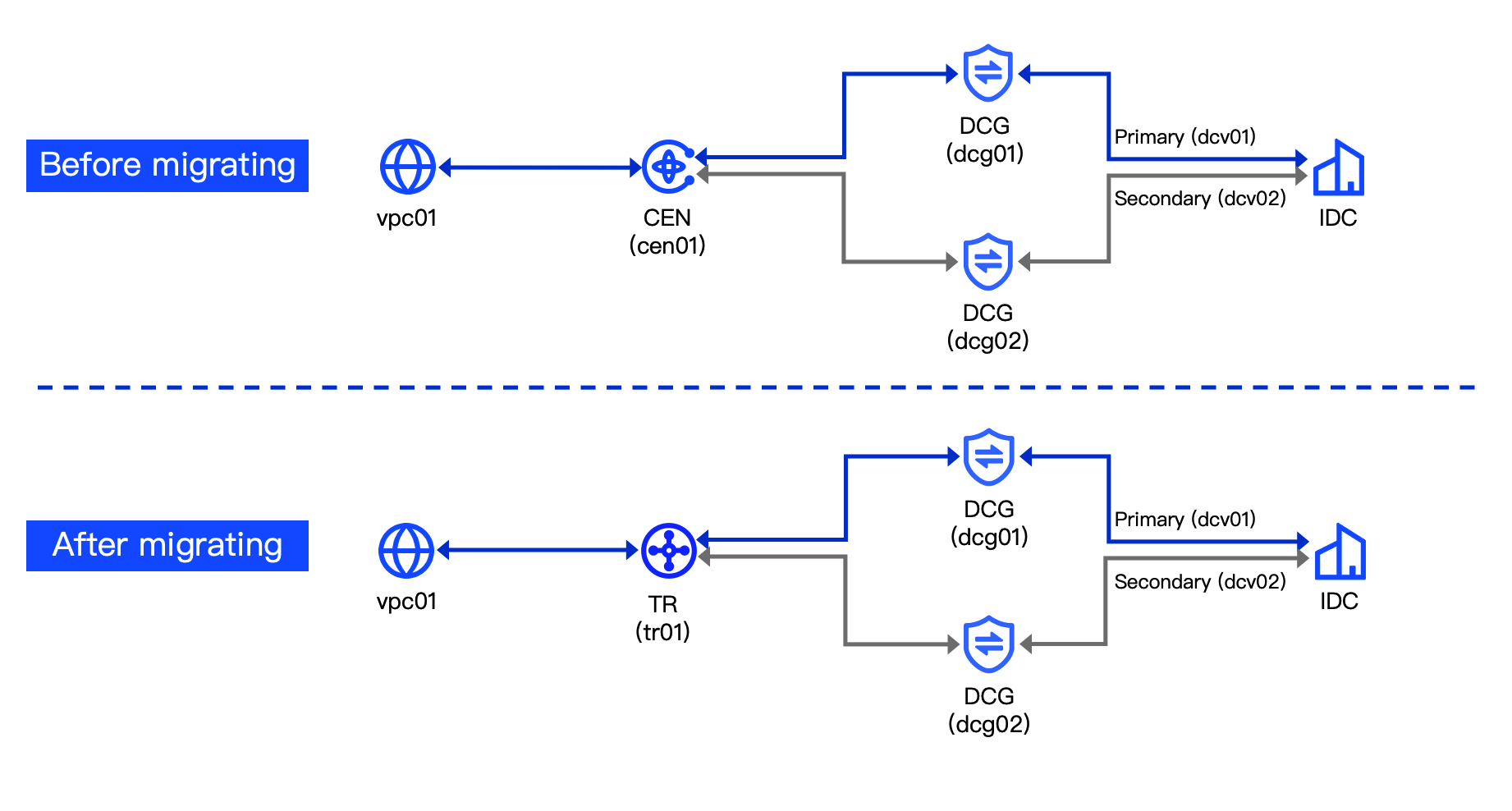
A company uses VolcanoEngine CEN and Direct Connect to connect a Virtual Private Cloud (VPC) with an on-premises data center, achieving private intercommunication between cloud and on-premises services. With business development, the company needs to migrate services to a TR. Leveraging its rich routing features enables flexible and scalable network architecture.
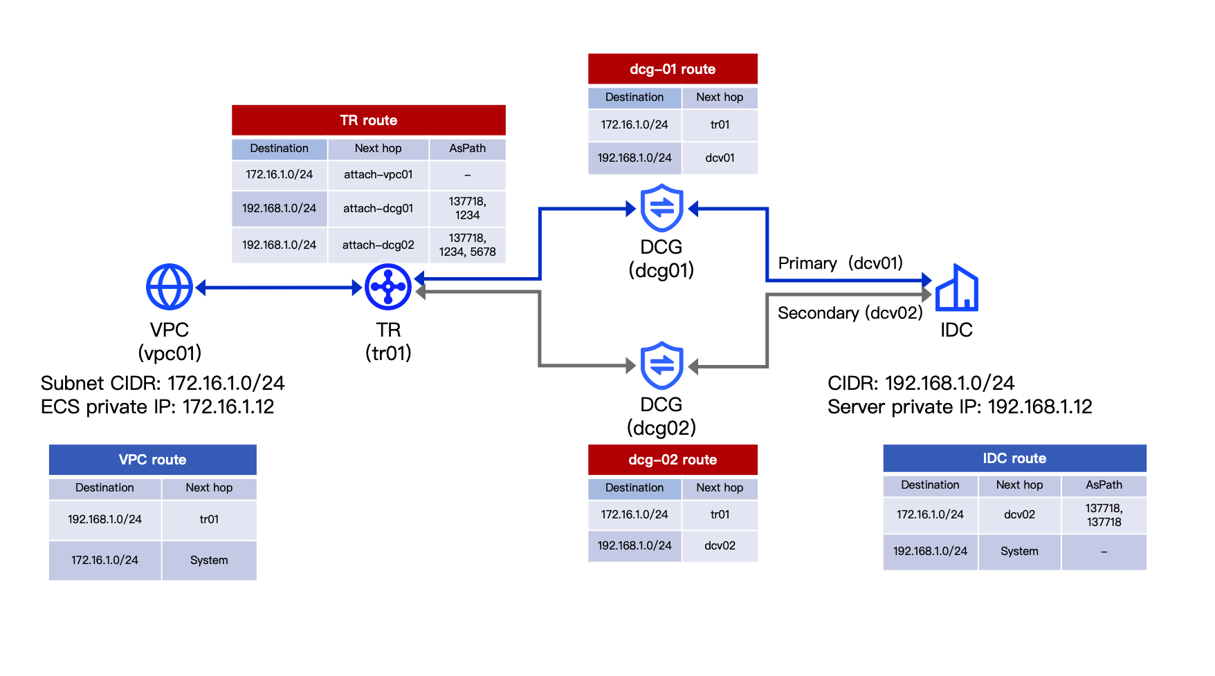
This section uses Direct Connect (DC) in active-standby redundancy to demonstrate the service migration procedure. The specific network architecture is shown in the diagram below.
Data planning
tip
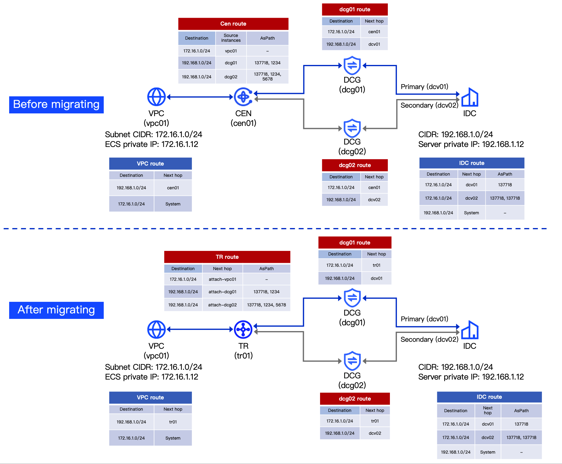
All ASNs for DC Gateways in this example are 137718 by default.
- Before and after migration, the configuration for Direct Connect remains unchanged. For configuration details, see Connecting an on-premises data center to a VPC via dual Direct Connects with BGP (active-standby redundancy).
- Before and after migration, the data and route planning for each network resource in the scenario are shown in the diagram below.
-
Prerequisites
Your VPC and on-premises data center are interconnected via CEN with dual active-standby DC links. For configuration details, see Connecting an on-premises data center to a VPC via dual Direct Connects with BGP (active-standby redundancy).
Configuration procedures
Step 1: Create a TR instance
Prepare a TR instance in the same region as the VPC you want to connect. For procedure, see Creating a Transit Router instance.
tip
When you create a TR instance, the system automatically creates a TR system route table. This section takes tr01-rtb-sys as an example.
Since network isolation is not involved in this example, only one TR route table is required.
Step 2: Connect TR and confirm routing
- Connect the VPC to the TR instance. For procedure, see Creating a VPC attachment.
- Association forwarding: Enable, and select the TR system route table (tr01-rtb-sys).
- Route learning: Enable, and select tr01-rtb-sys.
- Auto Publish Route: Disable.
- Unload the DC Gateway (dcg02) from the CEN. For procedure, see Removing network instances.
- Connect dcg02 to the TR instance. For procedure, see Creating a DC Gateway attachment.
- Association forwarding: Enable, and select the TR system route table (tr01-rtb-sys).
- Route learning: Enable, and select tr01-rtb-sys.
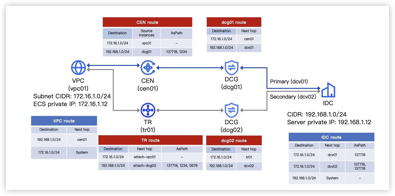
Now, vpc01 and the on-premises data center access each other via CEN through the primary DC (dcv01). Ensure that the routes in tr01 and dcg02 match the following diagram.
Step 3: Migrate bidirectional traffic to TR
warning
- Before proceeding, ensure that traffic from the on-premises data center to the VPC is routed to the primary DC (dcv01) via static routing. If BGP routing is in use, migrating this traffic to TR may cause service disruption.
- Migrating traffic to TR may cause seconds of disruption to your Cloud Load Balancer (CLB). Carefully assess the potential impact on your services.
- Add routes pointing to the TR to the VPC route table. For procedure, see Add a route.
- Destination CIDR should be smaller than the IDC subnet, for example, 192.168.1.12/32.
- Next Hop is tr01.
tip
Now, the VPC accesses the on-premises data center via TR through the secondary DC (dcv02). The traffic from the data center to the CLB in the VPC is still returned to the data center via CEN through the primary DC (dcv01).
- Adjust the AsPath attribute of the two BGP routes pointing to the DC links in the data center's route table. This will migrate on-premises-to-vpc01 traffic from dcg01 to dcg02.
- The shorter the AsPath, the higher the route priority. Therefore, the adjusted AsPath length of the secondary link should be shorter than that of the primary link. For example, the AsPath for the secondary link is 137718, so the primary link's AsPath is 137718, 137718.
- Unload dcg01 and vpc01 from the CEN to migrate vpc01-to-on-premises traffic to TR. For procedure, see Removing network instances.
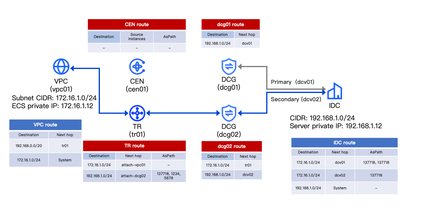
Now, vpc01 accesses the on-premises data center via TR through dcv02. The network architecture and routing of the cloud and on-premises resources are shown in the following diagram.
Step 4: Restore active-standby failover configuration for Direct Connect
- Enable auto publishing for the VPC attachment to synchronize the TR routes into the VPC route table. For procedure, see Enable auto publishing.
- Delete the custom route whose next hop is tr01 from the VPC route table. For procedure, see Delete a route.
- Connect dcg01 to the TR instance. For procedure, see Creating a DC Gateway attachment.
- Association forwarding: Enable, and select the TR system route table (tr01-rtb-sys).
- Route learning: Enable, and select tr01-rtb-sys.
- Adjust the AsPath attribute of the two BGP routes pointing to the DC links in the data center's route table. This will migrate on-premises-to-vpc01 traffic from dcg02 to dcg01.
- The shorter the AsPath, the higher the route priority. Therefore, the adjusted AsPath length of the primary link should be shorter than that of the secondary link. For example, the AsPath for the secondary link is 137718, 137718, and the primary link's AsPath is 137718.
Now, vpc01 and the on-premises data center access each other via TR through the primary and secondary DC links. The network architecture and routing of the cloud and on-premises resources are shown in the following diagram.
Result validation
- Log in to the server in the data center.
- Execute the ping command to verify network connectivity from the data center to the VPC.
- Ping the ECS in the VPC. For example: ping 172.16.1.12.
- View the monitoring data of the TR instance. For procedure, see Viewing monitoring data.
- If the inbound and outbound bandwidth is not 0, the traffic of the on-premises data center accessing the VPC is forwarded through the TR.
- View the monitoring data of DC Gateways (dcg01 and dcg02). For procedure, see Viewing monitoring data for Direct Connect.
- If the inbound bandwidth of dcg01 is not 0 and the inbound bandwidth of dcg02 has no data, the on-premises-to-VPC traffic is forwarded through the primary DC.
- Disconnect the primary link to simulate a fault scenario, then execute the ping command in the on-premises server, and Ping the ECS instance within the VPC.
- View the monitoring data of DC Gateways (dcg01 and dcg02). For procedure, see Viewing monitoring data for Direct Connect.
- If the inbound bandwidth of dcg01 is 0 while that of dcg02 is not, the on-premises-to-VPC traffic is forwarded through the secondary DC.
Now, you have completed the migration of bidirectional traffic between cloud and on-premises from CEN to TR.
Last updated: 2026.09.01 11:37:15
All rights reserved © Beijing Volcano Engine Technology Co., Ltd2024
