Transit Router
Transit Router


Document

- Documentation
 Transit RouterBest PracticesRestricting communication between VPCs or between a VPC and an on-premises data center by route policies
 Copy page
 Download PDF
Best Practices
Restricting communication between VPCs or between a VPC and an on-premises data center by route policies
Copy pageDownload PDFRestricting communication between VPCs or between a VPC and an on-premises data center by route policies
This topic describes how to restrict communication between Virtual Private Clouds (VPCs) or between a VPC and an on-premises data center by route policies.
Scenarios
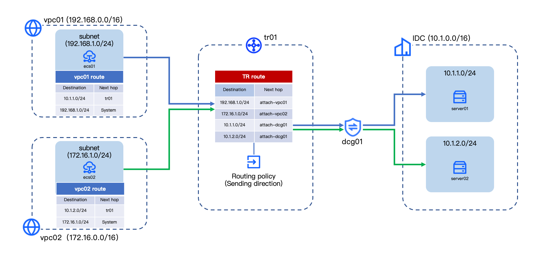
With route policies, you can restrict communication between VPCs or CIDR blocks. This achieves network isolation and simplifies route configuration of the Transit Router (TR). This example demonstrates how to configure route policies so that vpc01 cannot communicate with vpc02, vpc01 can only access CIDR block 1 in the data center, and vpc02 can only access CIDR block 2 in the data center. Specific network architecture is shown in the diagram below.
tip
You can also use multiple TR route tables to achieve network isolation. For configuration details, see Implementing interconnectivity and isolation between specified VPCs or Implementing interconnectivity between independent VPCs and a data center.
Prerequisites
Ensure the Direct Connect (DC) Connection and related resources for your on-premises data center accessing VolcanoEngine are ready. For detailed steps, see the first three steps in Direct Connect Quick start.
Configuration procedure
Step 1: Configure a basic network with global interconnection
- Follow the procedure in Creating a Transit Router instance to create a TR instance.
tip
The system automatically creates a system route table (named rtb-sys) for your TR instance. The following uses rtb-sys as an example.
- Follow the procedure in Creating a VPC attachment to connect vpc01 and vpc02 to the TR instance. The route configuration is described in the table below.
-
- Follow the procedure in Creating a DC Gateway attachment to connect the DC Gateway to the TR instance. The route configuration is described in the table below.
-
- Log in to the Elastic Compute Service (ECS) instance in the VPC, and execute the ping command to verify global interconnection between vpc01, vpc02, and the two on-premises CIDR blocks.
Step 2: Create a route policy
- Follow the procedure in Creating a route policy to create an outbound route policy. The configuration of the policy entries is described in the table below.
-
- Associate the route policy to rtb-sys based on Associate route policy to TR route table.
Result validation
- Log in to the ECS instance in vpc01. For procedure, see Logging on to a Linux instance or Logging on to a Windows instance.
- Execute the ping command to verify connectivity with vpc02, on-premises CIDR block 1, and on-premises CIDR block 2 in sequence.
- If vpc02 and the on-premises CIDR block 2 are unreachable and the on-premises CIDR block 1 is reachable, the expected isolation is met.
- Similarly, log in to the ECS instance in vpc02 and execute the ping command to verify network isolation.
Last updated: 2026.09.01 11:37:15
All rights reserved © Beijing Volcano Engine Technology Co., Ltd2024
