Transit Router
Transit Router


Document

- Documentation
 Transit RouterGetting StartedImplementing private interconnectivity and isolation between different VPCs (same account, same region)
 Copy page
 Download PDF
Getting Started
Implementing private interconnectivity and isolation between different VPCs (same account, same region)
Copy pageDownload PDFImplementing private interconnectivity and isolation between different VPCs (same account, same region)
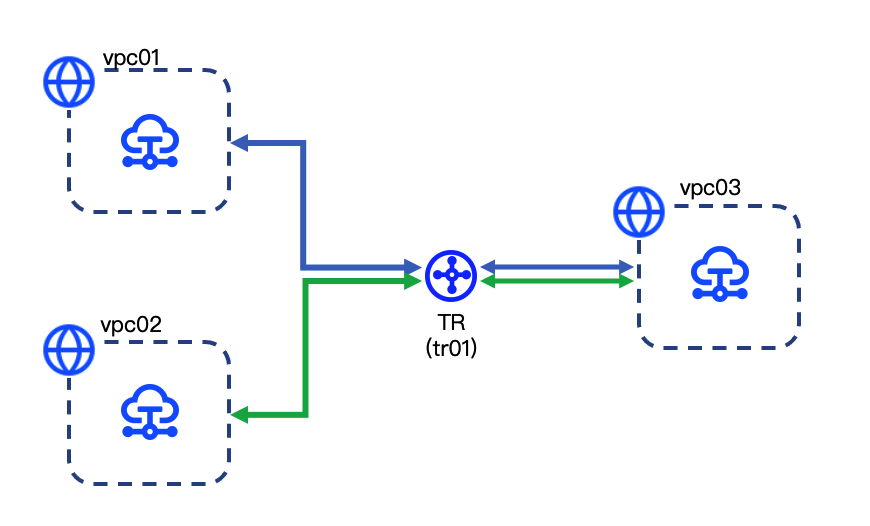
This section describes how to use Transit Router (TR) to connect vpc01 and vpc02 to vpc03 under the same account in the same region. It also explains how to isolate vpc01 from vpc02, as illustrated in the diagram below.
Prerequisites
- You have created three Virtual Private Clouds (VPCs) and their subnets. For procedure, see Building an IPv4 VPC.
tip
Ensure that the VPCs do not contain conflicting subnets. That is, no duplicate or overlapping CIDR blocks exist.
- You have created Elastic Compute Service (ECS) instances in the three VPCs. For procedure, see Purchasing an ECS instance.
Route planning
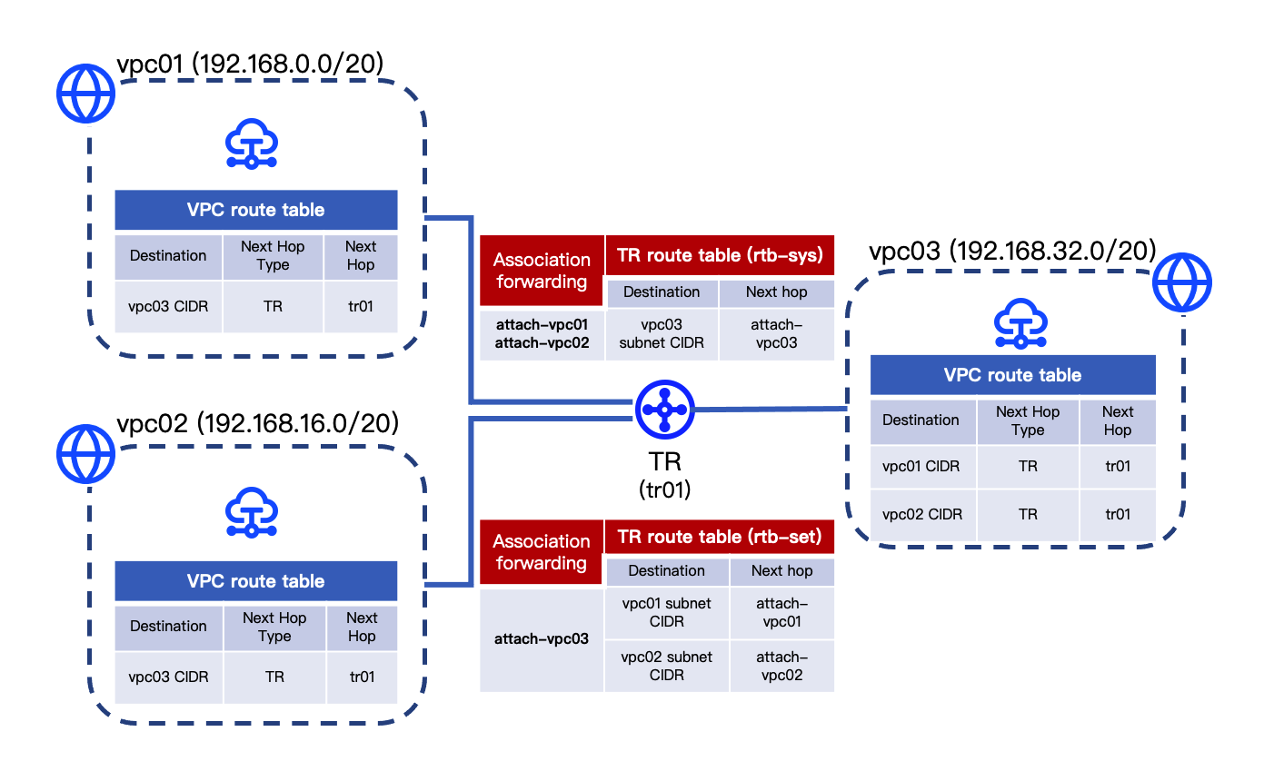
A single TR instance can use the same route table to forward traffic from multiple network instances that share a common destination. Thus, in this example, the TR uses one route table for forwarding from vpc01/vpc02 to vpc03, and a separate route table for the return path from vpc03 to vpc01/vpc02. This design necessitates at least two route tables, as illustrated in the following diagram.
tip
Routes in the VPC route tables illustrated above can be manually configured or automatically synchronized. This example uses automatic publishing. To manually configure VPC routes, see Achieving interconnectivity and isolation between VPCs.
Configuration procedures
- Create a TR instance: Create a TR instance to host the TR service.
- Create a TR custom route table: Create a custom route table to receive and forward network traffic along with the TR system route table.
- Create an attachment and configure routing: Create three attachments to separately connect the TR instance and three VPCs. On the TR side, configure association forwarding and route learning to control the traffic flow to and from these VPCs. On the VPC side, configure auto publishing to control flow direction.
- View TR and VPC routes: Review that the routes of the TR instance and three VPCs meet expectations.
- Validation: Run ping to verify the connectivity between ECS instances in different VPCs to ensure that the VPCs are connected and isolated as expected.
Configuration procedures
Step 1: Create a TR instance
- Log in to the Transit Router console.
- In the top menu bar, select the target project and region.
- Click Create TR and configure related parameters based on the table below.
-
- Click Create to complete the creation of the TR instance.
tip
When you create a TR instance, the system automatically creates a system route table for it. Record the name of this system route table (rtb-sys). The following uses rtb-sys as an example.
Step 2: Create a TR custom route table
- Click the name of the target TR instance.
- In the zone below Basic information, select the Route Table tab.
- Click Create Route Table to the right of the route table list, and type rtb-set as the route table name.
- Click Create to complete the creation of the TR route table.
Step 3: Create an attachment and configure routing
Create three attachments to connect to vpc01, vpc02, and vpc03 separately by the following steps.
- In the section below Basic information, select the Intra-region attachment tab.
- Click Create attachment, and complete the basic configuration for the network instance attachment based on the table below.
-
- Complete the route configuration for the network instance attachment based on the table below.
-
- Click Buy now to complete the action.
Step 4: View TR and VPC routes
- View the TR route tables (rtb-sys and rtb-set) in sequence, and confirm that the route entries listed below exist.
-
- View the system routes in the route tables of vpc01, vpc02, and vpc03 in sequence, and confirm that the route entries listed below exist.
-
Result validation
The following verification steps take a Linux-based ECS as an example:
- Remotely log in to the ECS instance in vpc01. For procedure, see Logging on to a Linux instance.
- Execute the ping command to connect the private IP addresses of respective ECS instances in vpc02 and vpc03, verifying network connectivity.
- The ECS instances in vpc01 and vpc02 are mutually isolated and cannot ping each other.
- The ECS instances in vpc01 and vpc03 can communicate and ping each other successfully.
- Similarly, remotely log in to the ECS instances in vpc02 and vpc03 to verify connectivity between vpc02, vpc03, and another VPC.
Last updated: 2026.09.01 11:37:09
All rights reserved © Beijing Volcano Engine Technology Co., Ltd2024
