Transit Router
Transit Router


Document

- Documentation
 Transit RouterBest PracticesImplementing secure mutual access between different VPCs
 Copy page
 Download PDF
Best Practices
Implementing secure mutual access between different VPCs
Copy pageDownload PDFImplementing secure mutual access between different VPCs
This topic describes how to forward access requests to a secure network deployed with a VolcanoEngine Cloud Firewall or third-party firewall via Transit Router (TR). This setup enables secure intercommunication between two Virtual Private Clouds (VPCs).
Scenarios
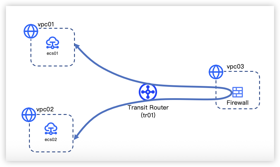
A company deployed private services within three VPCs in VolcanoEngine China (Guangzhou). Among them, Business A and Business B are respectively deployed in vpc01 and vpc02, and the firewall software is deployed in vpc03. For business security considerations, the traffic between Business A and Business B must pass through the firewall software for traffic scrubbing. The specific scenario is shown in the following diagram.
tip
Data planning
The data planning for secure intercommunication of traffic between different VPCs in the same region is shown below. Specific parameters for each cloud service in the networking scenario are shown in Table 1 and Table 2.
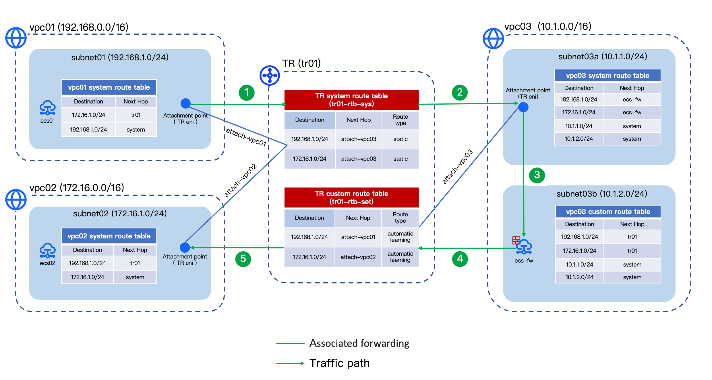
The description of traffic paths in the above figure is as follows (taking access from vpc01 to vpc02 as an example, the principle of vpc02 accessing vpc01 is similar):
- After Elastic Compute Service (ECS) ecs01 initiates an access request to ecs02. According to the route table of the VPC linked to ecs01's subnet, the system matches the route entry with next hop tr01 and forwards the access request to tr01.
- The TR forwards the access request to attach-vpc03 after matching the destination CIDR block based on the TR system route table associated with attach-vpc01.
- In vpc03, the system references the VPC route table associated with the subnet that the TR network interface belongs to. It matches the route entry with a next hop of ecs-fw and forwards the request to the ecs-fw.
- After the traffic of the access request is scrubbed through the firewall in the ECS ecs-fw, based on the VPC route table associated with the subnet to which the ECS belongs, the system matches the route entry with the next hop of tr01 and forwards the request to the tr01.
- The TR uses the TR custom route table for attach-vpc03's associated forwarding to match the Destination CIDR Block and finally delivers the request to vpc02, achieving vpc01's secure access to vpc02.
Table 1 VPC
Table 2 TR
Prerequisites
- You have created necessary VPCs and their subnets. For procedure, see Creating a VPC.
- You have created a custom route table for vpc03 and associated the custom route table with the subnet to which the ecs-fw belongs. For procedure, see Creating a route table and Associate a subnet.
- You have created Elastic Compute Service (ECS) instances in all VPCs. For procedure, see Purchasing an ECS instance.
- You have deployed a firewall in ecs-fw, and allowed the CIDR blocks of vpc01 and vpc02 in the firewall.
tip
- You have created required TR instances and their custom route tables. For procedure, see Creating a Transit Router instance and Creating a route table.
Configuration procedures
Step 1: Create an attachment between the TR instance and the VPC
Follow the procedure of Creating a VPC attachment to create 3 VPC attachments, separately connecting vpc01, vpc02 and vpc03. The parameter values for this example are shown in the table below.
- Basic configuration
-
- Route configuration
-
Step 2: Configure a TR route table
- Configure routes in the TR system route table to forward access requests from vpc01 and vpc02 to vpc03.
- For procedure, see Create a static route. The routes configured for this example are listed in the table below.
- No.Destination CIDRNext Hop1192.168.1.0/24attach-vpc032172.16.1.0/24attach-vpc03
- Confirm whether the subnet routes of vpc01 and vpc02 exist in the TR custom route table.
- Yes. Proceed to Step 3: Configure a VPC route table.
tip
In this example, skip this step since route learning for the attachments connecting vpc01 and vpc02 is enabled in Step 1.
- No. Follow the procedure of Create a route learning rule to create separate rules on the TR custom route table for attach-vpc01 and attach-vpc02. After configuration, the routes in the TR custom route table are as shown in the following table.
- No.Destination CIDRNext Hop1192.168.1.0/24attach-vpc012172.16.1.0/24attach-vpc02
Step 3: Configure a VPC route table
- Confirm whether the route tables of vpc01 and vpc02 contain a route with Next Hop as tr01.
- Yes. Skip this step and proceed to Step 2.
tip
Since Auto Publish Route is enabled for the attachment connecting vpc01 in Step 1, proceed to Step 2.
- No. Follow the procedure of Enable auto publishing to enable Auto Publish Route for respective attachments (attach-vpc01 and attach-vpc02). After configuration, the auto-published routes in the system route tables of vpc01 and vpc02 are as shown in the following table.
- VPC nameRoute entry typeDestination CIDRNext Hopvpc01System route172.16.1.0/24tr01vpc02System route192.168.1.0/24tr01
- Configure the vpc03 system route table to forward requests accessing vpc01 and vpc02 to ecs-fw.
- Add the following routes to the vpc03 system route table. For procedure, see Add a route.
- No.Route entry typeDestination CIDRNext Hop1Custom route192.168.1.0/24ecs-fw2Custom route172.16.1.0/24ecs-fw
- Configure the vpc03 custom route table to forward requests accessing vpc01 and vpc02 to tr01.
- Enable Auto Publish Route for attach-vpc03 by seeing Enable auto publishing.
- After configuration, the following routes are automatically added to the vpc03 custom route table.
- No.Route entry typeDestination CIDRNext Hop1System route192.168.1.0/24tr012System route172.16.1.0/24tr01
Step 4: Configure ecs-fw to enable IP forwarding (optional)
- Log in to ecs-fw. For procedure, see Logging on to a Linux instance or Logging on to a Windows instance.
- Execute the following command to review whether the ECS has IP forwarding enabled.
- cat /proc/sys/net/ipv4/ip_forward
- The response is 1, indicating IP forwarding is enabled. No further steps are needed.
- The response is 0, indicating IP forwarding is not enabled. Continue with the following steps.
- Execute the following command to open the sysctl.conf file.
- vi /etc/sysctl.conf
- Press i to enter edit mode, change the value of net.ipv4.ip_forward to 1 to enable IP forwarding.
tip
If the sysctl.conf file does not contain a net.ipv4.ip_forward field, manually add net.ipv4.ip_forward = 1 at the end of the file.
- Press esc to exit the edit mode, enter :wq to save and exit the file.
- Execute the following command to restart the system for the configuration to take effect.
- sysctl -p /etc/sysctl.conf
Result validation
- Log in to the ECS instance (ecs01) in vpc01. For procedure, see Logging on to a Linux instance or Logging on to a Windows instance.
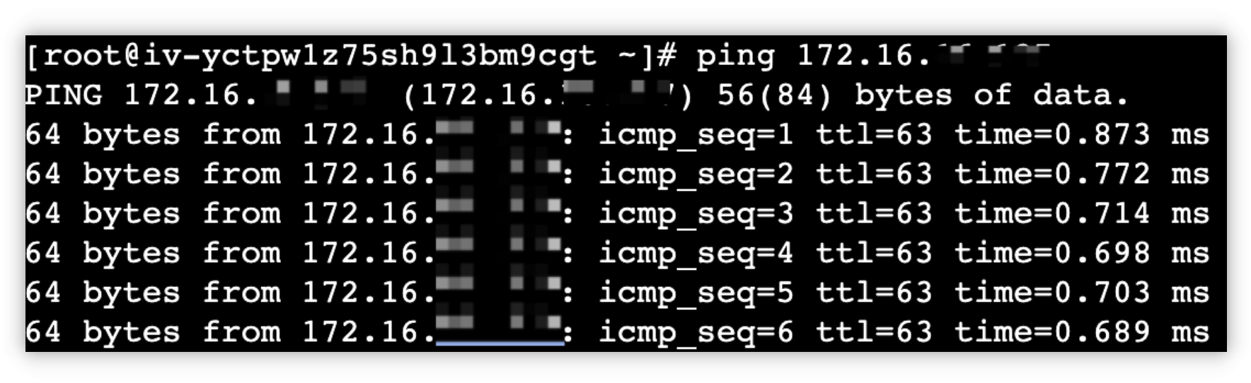
- Execute the ping command to connect the ECS within vpc02, verifying that vpc01 can access vpc02 properly.
- If the response is the same as the diagram below, access is normal.
-
- Similarly, log in to the ECS instance (ecs02) in vpc02 and execute the ping command to verify that vpc02 can access vpc01 properly.
- Review the monitoring data of attach-vpc03. If the inbound and outbound bandwidth is not 0, the mutual traffic between vpc01 and vpc02 is forwarded through vpc03.
- For procedure, see Viewing monitoring data.
- Check the firewall to confirm that mutual traffic between vpc01 and vpc02 is scrubbed by the firewall.
Last updated: 2026.09.01 11:37:15
All rights reserved © Beijing Volcano Engine Technology Co., Ltd2024
